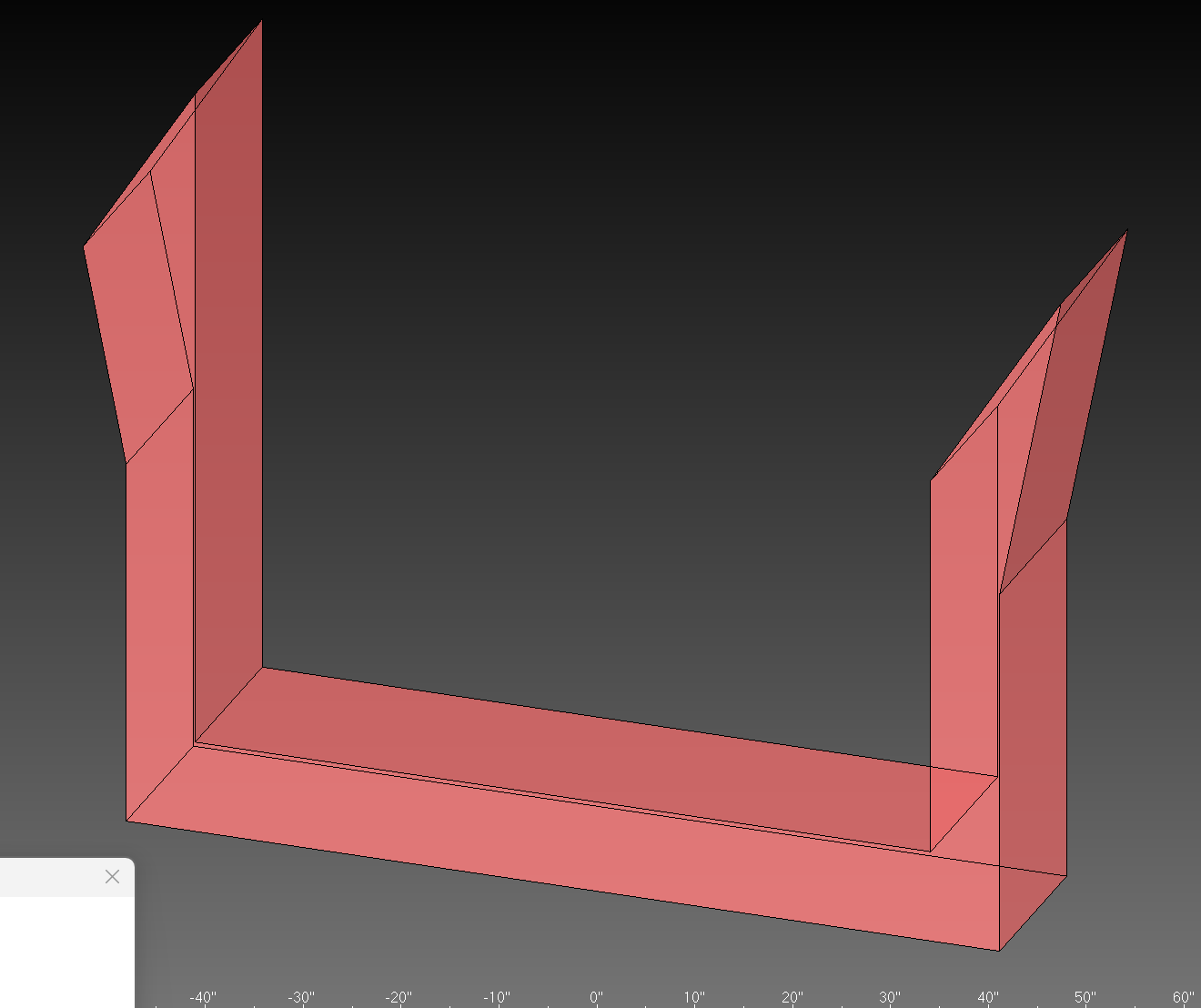
The Danger Zone Marking feature automatically detects and addresses potentially hazardous sharp edges on fixture blades. Sharp blade tips can cause injury during handling and should be either clearly marked or removed.
⚠️ Safety First
Sharp blade edges are a common cause of cuts and injuries in manufacturing environments. This feature helps identify and mitigate these hazards automatically.
| Feature | Description | Status |
|---|---|---|
| Detection | Identifies sharp external corners on thin blade faces | DONE |
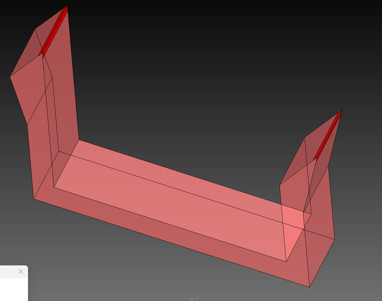
| Marking | Colors dangerous edges red for visibility | DONE |
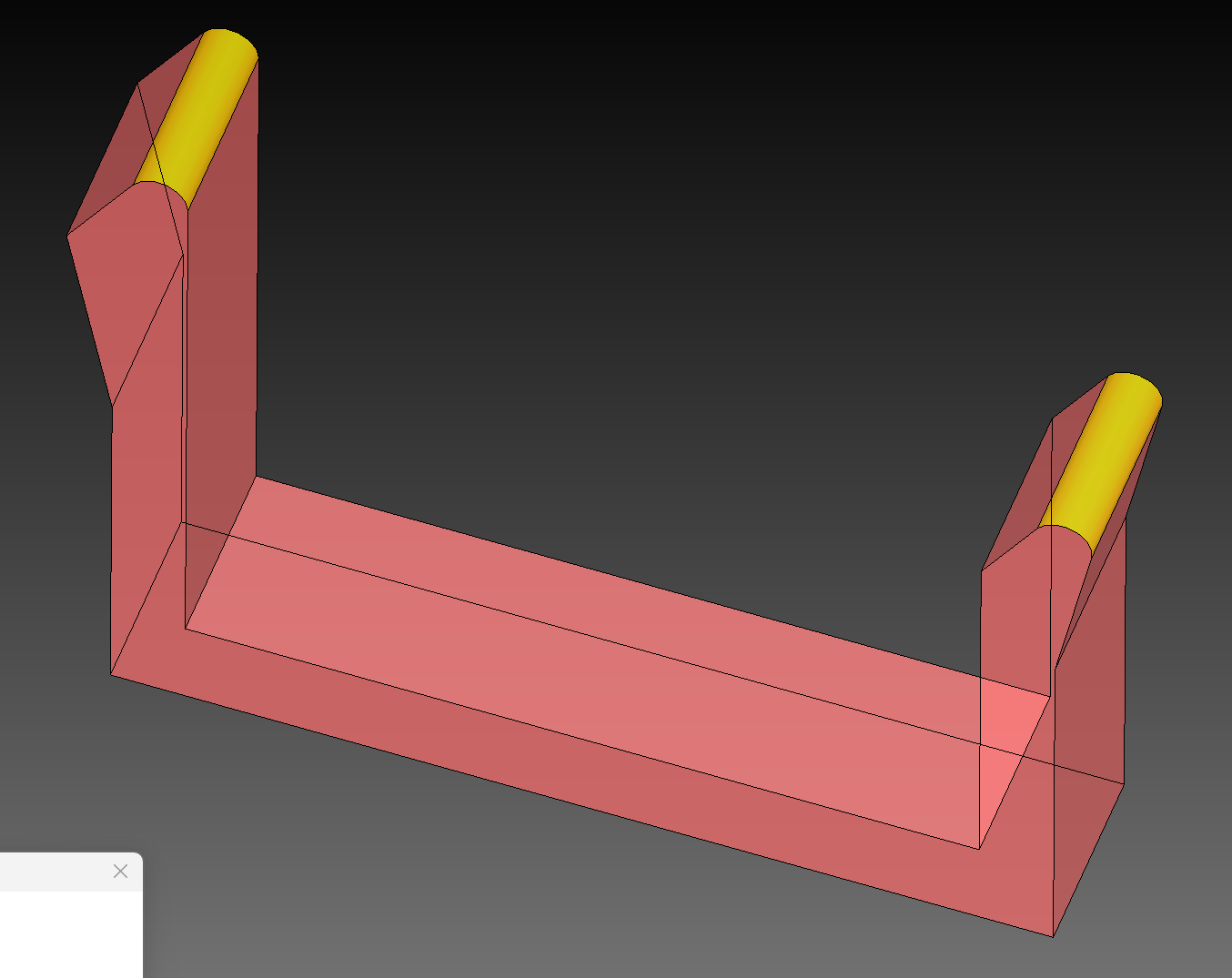
| Blending | Applies safety radius to remove sharp tips | DONE |