🆕 Locator Plate System
A robust plunger mounting system using top and bottom locator plates instead of threading directly into the blade. This provides better strength, serviceability, and alignment.
Assembly Overview
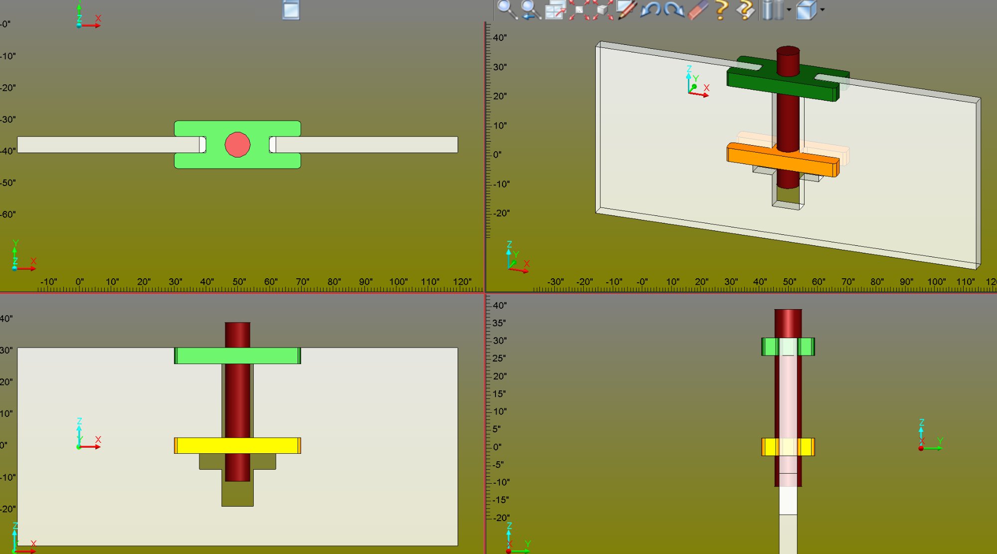
Four-view assembly showing the plunger mounting system:
Top-Left: Front view | Top-Right: Isometric view
Bottom-Left: Side view | Bottom-Right: End view
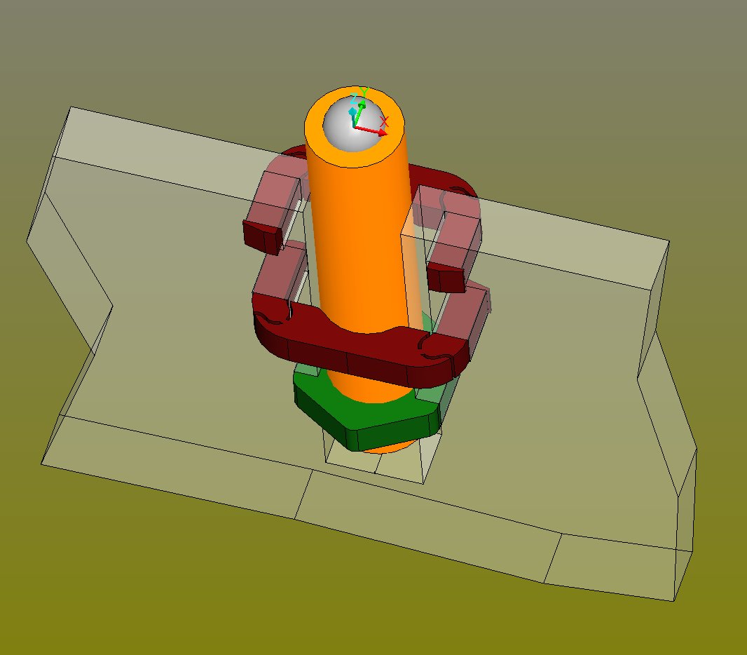
Component Stack (Top to Bottom)
| Component | Color | Function |
|---|
| Plunger Ball |
Red (top) |
Spring-loaded ball contacts the workpiece |
| Top Locator Plate |
Green |
Sits in machined recess; prevents vertical movement |
| Blade |
Gray |
Has pocket machined through for assembly |
| Bottom Locator Plate |
Orange |
Stabilizes nut; slightly different shape than top |
| Nut |
(captured) |
Threads onto plunger body; held by bottom plate |
| Plunger Body |
Dark Red |
Threaded cylinder with internal spring |
Cross-Section Diagram
PLUNGER MOUNTING ASSEMBLY - CROSS SECTION
═══════════════════════════════════════════
┌───┐
│ ● │ ◀── Plunger ball (contacts part)
└─┬─┘
│
┌─────────────┼─────────────┐
│ ░░░░░░░░░░░│░░░░░░░░░░░ │ ◀── GREEN: Top Locator Plate
│ ░░░░░░░░░░░│░░░░░░░░░░░ │ (sits in blade recess)
└─────────────┼─────────────┘
══════════════════╪══════════════════ ◀── BLADE (gray)
║ ║ ║ with pocket cut through
║ ┌───────────┼───────────┐ ║
║ │ ▓▓▓▓▓▓▓▓▓│▓▓▓▓▓▓▓▓▓ │ ║ ◀── ORANGE: Bottom Locator
║ │ ▓▓▓▓▓▓▓▓▓│▓▓▓▓▓▓▓▓▓ │ ║ (stabilizes nut)
║ └───────────┼───────────┘ ║
║ │ ║
╚═════════════════╪═════════════════╝
│
┌───┴───┐
│ NUT │ ◀── Captured nut
└───┬───┘
│
│ ◀── Plunger threaded body
│
▼
(extends below blade)
Key Design Features
| Feature | Benefit |
|---|
| Recessed Top Plate |
Green plate sits in a shallow step machined into blade top surface - prevents upward movement under load |
| Captured Nut |
Nut is held in pocket by orange plate - cannot spin or fall out during adjustment |
| No Threading into Blade |
Plunger held mechanically by plates, not by threads in potentially thin blade material |
| Fully Serviceable |
Remove top plate → unthread plunger → replace → reassemble |
| Perpendicular Alignment |
Locator plates ensure plunger is exactly perpendicular to blade surface |
Assembly Sequence
- Machine blade pocket - Cut rectangular pocket through blade with top recess
- Insert bottom plate - Orange locator plate goes in from bottom
- Insert nut - Drop nut into pocket, resting on bottom plate
- Thread plunger - Insert plunger from top, thread into nut
- Install top plate - Green plate drops into recess, capturing assembly
- Secure - Optional: spot weld or adhesive on top plate edges
Dimensional Parameters
| Parameter | M5 | M6 | M8 | Description |
|---|
pocketWidth | 14mm | 16mm | 20mm | Pocket width in blade |
pocketLength | 14mm | 16mm | 20mm | Pocket length in blade |
recessDepth | 2mm | 2mm | 3mm | Top plate recess depth |
topPlateThickness | 2mm | 2mm | 3mm | Green plate thickness |
bottomPlateThickness | 2mm | 2mm | 3mm | Orange plate thickness |
nutHeight | 4mm | 5mm | 6.5mm | Standard nut height |
plungerDiameter | 5mm | 6mm | 8mm | Plunger body OD |
⚠️ Blade Thickness Requirement
Minimum blade thickness = recessDepth + topPlateThickness + bottomPlateThickness + nutHeight + clearance
For M6: 2 + 2 + 2 + 5 + 1 = 12mm minimum blade thickness
For thinner blades, use the T-slot mounting system instead (see below).
- ✓ Design concept finalized
- ○ Pocket profile generation macro
- ○ Top/bottom plate DXF generation
- ○ JSON schema integration
- ○ Automatic placement algorithm
📦 Deliverables
fxPlungerPocket.ovm - Pocket and recess generation
fxLocatorPlates.ovm - Plate profile generation
plunger_top_plate_M6.dxf - Laser cut files
plunger_bottom_plate_M6.dxf - Laser cut files