🔗 Blade Retention Systems

Blade-to-Blade Interlocking and Blade-to-Baseplate Mounting

Overview

Blade retention covers two distinct areas:

  1. Blade-to-Blade - How blades interlock with each other at intersections
  2. Blade-to-Baseplate - How blades mount into the fixture baseplate

Document Sections

SectionTopic
Blade-to-Blade InterlockingN-blade / U-blade slot systems, clearances, crossover positioning
Blade-to-Baseplate MountingTab/slot systems, locking mechanisms, captured nut mounting
JSON ConfigurationComplete schema for all retention options

⚠️ Not to be confused with Part Retention

Blade Retention = How blades connect to each other and baseplate (this page)

Part Retention = How the workpiece is held by blades (see Part Retention)

🔗 Blade-to-Blade Interlocking

When two blades intersect (typically at 90°), one blade has a U-slot (receiver) and the other has an N-tab (insert). This section covers the geometry and clearance requirements.

Key Terms

TermDescription
U-BladeReceiver blade with slot cut into it
N-BladeInsert blade with tab/tongue that engages the slot
Crossover HeightVertical position where blades intersect
Crossover GapClearance or radius between intersecting faces

Slot Clearance Configuration

Clearance Dimensions

U-BLADE SLOT CLEARANCES (Top View) ══════════════════════════════════════════════════ ┌─── clearanceLeft │ ▼ ┌───────────────────────────┐ │ │ │ │ │ │ N-tab │ │ │ │ │ │ │ │ │◀──────────┼─── clearanceRight │ │ │ │ └───────────────────────────┘ │ │ │◀─────▶│ slot width additionalClearance = extra on BOTH sides
ParameterDescriptionDefault
clearanceLeftGap on left side of N-tab0.1 mm
clearanceRightGap on right side of N-tab0.1 mm
additionalClearanceExtra clearance added to both sides0 mm

Total slot width = N-tab thickness + clearanceLeft + clearanceRight + (2 × additionalClearance)

Crossover Gap / Radius

Where the upper N-blade face crosses the lower U-blade face, you can specify either a gap (clearance) or a radius to ensure they don't touch:

CROSSOVER DETAIL (Side View at Intersection) ════════════════════════════════════════════════════ OPTION A: Gap (flat clearance) N-blade ────────┐ │ ┌──────┴──────┐ │ GAP ↕ │ ◀── crossoverGap (e.g., 2mm) ─────────┴─────────────┴───────── U-blade OPTION B: Radius (curved clearance) N-blade ────────┐ │ ╭───┴───╮ ╱ ╲ ◀── crossoverRadius (e.g., 3mm) ──────────╯ ╰────────── U-blade
ParameterDescriptionUse Case
crossoverGapFlat vertical gap between blade facesSimple clearance, easy to machine
crossoverRadiusRadiused transition between facesStress relief, smoother load transfer

If both are specified, crossoverRadius takes precedence.

Crossover Height Positioning

Height Options

The crossover point (where U-slot is positioned) can be specified as:

CROSSOVER HEIGHT OPTIONS ════════════════════════════════════════════════════ ┌─────────────────────────┐ ◀── Blade top (100%) │ │ │ │ │ ═════════ │ ◀── Crossover at 50% (ratio mode) │ │ OR fixed at 25mm (fixed mode) │ │ │ │ └─────────────────────────┘ ◀── Blade bottom (0%) Total height at intersection = H RATIO MODE: crossoverHeight = H × ratio FIXED MODE: crossoverHeight = fixedValue (always)
ModeParameterDescription
Ratio crossoverRatio: 0.5 50% of intersection height (scales with blade)
Fixed crossoverFixed: 25 Always 25mm from bottom (constant)

When to Use Each Mode

ModeBest ForExample
Ratio Variable height blades, consistent proportions Crossover always at center regardless of blade height
Fixed Consistent baseplate clearance, robot access All crossovers at 30mm for robot gripper clearance

⚠️ Height Validation

If crossoverFixed exceeds the actual blade intersection height, the system will:

  • Warn the user
  • Fall back to ratio mode (50%)

Keyhole Slot Variations

Slot Pattern Reference

Keyhole Slot Variations

Six keyhole slot variations showing different configurations for blade interlocking.

Retention Types

TypeDescriptionServiceability
keyholeWide entry hole + narrow slot lockTool-free assembly
friction-slotSimple slot, interference fitModerate - pry out
cross-pinBoth blades slotted, pin locksExcellent - remove pin
weld-onlyNo mechanical interlockPermanent
noneNo retention (bridge blades)N/A

🔩 Blade-to-Baseplate Mounting

Blades must be securely mounted to the fixture baseplate. Multiple methods are available depending on serviceability requirements and load conditions.

Mounting Method Overview

MethodDescriptionServiceabilityStrength
Tab + Slot Blade tabs fit into baseplate slots Excellent Medium
Tab + Slot + Shift-Lock Tabs shift sideways to lock Good (with clip) High
Captured Nut + Screw Screw from below into blade foot Excellent High
Direct Weld Blade welded to baseplate None (permanent) Very High

Tab + Slot Mounting

Basic Tab/Slot System

Blade foot has tabs that drop into matching slots in the baseplate:

TAB + SLOT MOUNTING (Side View) ═══════════════════════════════════════════════════ BLADE ┌─────────────────┐ │ │ │ │ │ │ └──┬─────────┬────┘ │ TAB │ │ │ │ │ ◀── Tab depth options: │ │ - Through (full thickness) │ │ - Partial (fixed depth) │ │ - User-defined ═══╪═════════╪═══════════ BASEPLATE │ │ │ SLOT │ └─────────┘

Tab Depth Options

OptionDescriptionUse Case
through Tab passes completely through baseplate Maximum engagement, visual confirmation
partial Tab stops at percentage of baseplate thickness Clean underside, calculated depth
fixed Tab depth is fixed value (e.g., 10mm) Consistent depth regardless of baseplate

Slot Configuration

BASEPLATE SLOT (Top View) ═════════════════════════════════════════ ┌─────────────────────────────────────┐ │ │ │ ┌───────────────────────┐ │ │ │ │ │ │ │ SLOT │ │ ◀── slotLength │ │ │ │ │ └───────────────────────┘ │ │ │ │ │ ▼ │ │ slotWidth │ │ (blade thickness + clearance) │ │ │ └─────────────────────────────────────┘ BASEPLATE
ParameterDescriptionDefault
slotWidthBlade thickness + clearanceauto + 0.2mm
slotLengthLength of slot in baseplateblade length
slotDepthDepth of slot (or "through")through
tabCountNumber of tabs per bladeauto (based on length)
tabSpacingDistance between tabs100mm

Shift-Lock Tab System

🆕 Locking Mechanism

Tabs pass through baseplate, then blade shifts sideways to lock. A retaining clip prevents the blade from shifting back.

Shift-Lock Operation

SHIFT-LOCK MECHANISM (Top View - Looking Down) ══════════════════════════════════════════════════════════ STEP 1: Insert blade vertically BLADE │ ┌────────────┼────────────┐ │ │ │ │ ┌──────┴──────┐ │ │ │ SLOT │ │ BASEPLATE │ └─────────────┘ │ │ ↓ │ └─────────────────────────┘ STEP 2: Shift blade LEFT to lock BLADE │ ┌────────────┼────────────┐ │ ┌────┴────┐ │ │ │ TAB │ │ │ ◀────│ SHIFTED │ │ BASEPLATE │ │ │ │ │ └─────────┘ │ └─────────────────────────┘ Tab now underlaps baseplate edge STEP 3: Insert retaining clip ┌─────────────────────────┐ │ CLIP ┌─────────┐ │ │ ████ │ TAB │ │ │ ████───│ LOCKED │ │ BASEPLATE │ ████ │ │ │ │ └─────────┘ │ └─────────────────────────┘ Clip prevents shift-back

Lock Geometry

ParameterDescriptionDefault
shiftDistanceHow far blade shifts to lock5mm
lockLipUndercut depth in baseplate3mm
clipSlotSlot for retaining clipenabled
clipTypeSheet metal spring clip design"nucleo"

Retaining Clip (Nucleo Style)

The same clip design used in Nucleo fixtures - sheet metal spring clip that snaps into a slot:

RETAINING CLIP PROFILE ══════════════════════════════════════════ ┌─────────────────────────┐ │ ○ ○ │ ◀── Snap tabs │ \ / │ │ \ / │ │ \_______█_______/ │ ◀── Blade contact │ │ │ └────────────┴────────────┘ ↓ Locks against blade Prevents shift-back

📦 Generated Files

baseplate_shift_slot.dxf - Slots with lock geometry

blade_lock_clip.dxf - Retaining clip profile (laser cut)

Captured Nut + Screw Mounting

🆕 Screw-Up Mounting

Similar concept to the plunger T-slot mount, but inverted. A captured nut in the blade foot allows a screw from below to secure the blade to the baseplate.

Assembly Cross-Section

CAPTURED NUT MOUNTING (Side View) ════════════════════════════════════════════════════════ BLADE ┌─────────────────────┐ │ │ │ │ │ │ └──────────┬──────────┘ │ ┌───────┴───────┐ │ ┌───────┐ │ ◀── Nut pocket in blade foot │ │ NUT │ │ │ └───┬───┘ │ │ │ │ ══════════╪═══════╪═══════╪══════════ BASEPLATE │ │ │ │ │ │ ◀── Clearance hole in baseplate └───────┼───────┘ │ ┌──┴──┐ │SCREW│ ◀── Screw from below │ ▼ │ └─────┘ Screw threads into captured nut, pulling blade tight to baseplate

Component Details

ComponentDescription
Nut PocketRecess in blade foot sized to capture nut
Captured NutStandard hex nut held in pocket (can't spin)
Baseplate HoleClearance hole for screw to pass through
ScrewSocket head or countersunk from below

Dimensional Parameters

ParameterM5M6M8Description
nutWidth8mm10mm13mmNut across flats
nutHeight4mm5mm6.5mmNut thickness
pocketDepth5mm6mm8mmPocket in blade foot
clearanceHole5.5mm6.5mm9mmBaseplate hole diameter
countersinkoptionaloptionaloptionalFor flush screw heads

👍 Advantages

  • Positive clamping - Screw pulls blade down firmly
  • Fully serviceable - Remove screw, blade lifts out
  • Adjustable - Can tighten or loosen as needed
  • No welding - Completely mechanical

👎 Disadvantages

  • Access required - Need access to underside of baseplate
  • More components - Nut + screw per location
  • Thicker blade foot - Must accommodate nut pocket

🔄 Mounting Method Comparison

Criteria Tab + Slot Shift-Lock Captured Nut Weld
Serviceability Excellent Good Excellent None
Strength Medium High High Very High
Assembly Time Fast Medium Medium Slow
Component Count 0 1 (clip) 2 (nut, screw) 0
Underside Access Optional No Required No
Best For Light duty, prototypes Production fixtures Heavy duty, serviceable Permanent fixtures

💡 Selection Guide

  • Prototype / light loads → Tab + Slot
  • Production / medium loads / no underside access → Shift-Lock
  • Heavy loads / full serviceability → Captured Nut
  • Permanent / maximum strength → Weld

📡 JSON Configuration

Complete Blade Retention Schema

"bladeRetention": { // ═══════════════════════════════════════════════════════ // BLADE-TO-BLADE INTERLOCKING // ═══════════════════════════════════════════════════════ "bladeToBlade": { "type": "keyhole", // "keyhole" | "friction-slot" | "cross-pin" | "weld-only" | "none" // --- Slot Clearances --- "clearanceLeft": 0.1, // mm - gap on left side of N-tab "clearanceRight": 0.1, // mm - gap on right side of N-tab "additionalClearance": 0, // mm - extra on BOTH sides // --- Crossover Configuration --- "crossover": { "mode": "ratio", // "ratio" | "fixed" "ratio": 0.5, // 0.0-1.0 (if mode=ratio) "fixedHeight": 25, // mm (if mode=fixed) "gapOrRadius": "gap", // "gap" | "radius" "gap": 2, // mm clearance between faces "radius": 3 // mm fillet radius (if gapOrRadius=radius) }, 
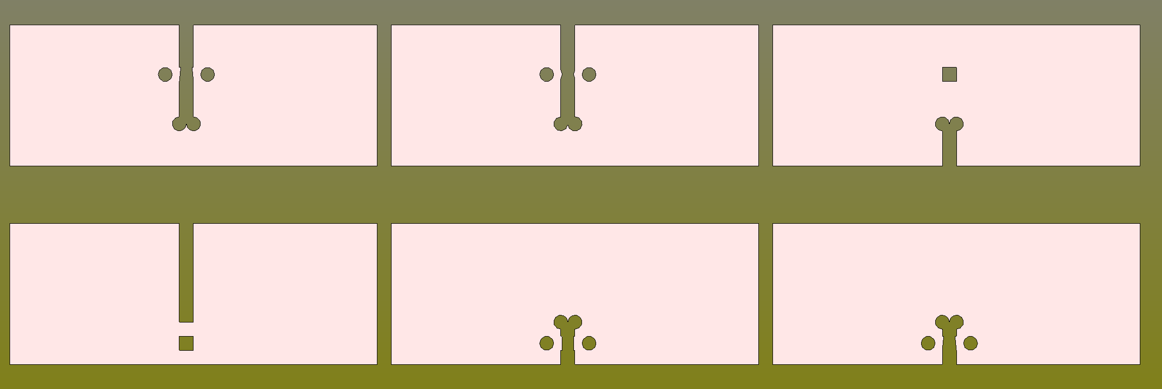
// --- Keyhole Options --- "keyhole": { "enabled": true, "entryDiameter": "auto", // "auto" = slot width × 2 "position": "bottom" // "top" | "bottom" }, // --- Relief Holes --- "reliefHoles": { "enabled": true, "count": 2, "diameter": 4, // mm "offsetFromSlot": 8 // mm from slot centerline }, // --- Alignment Hole --- "alignmentHole": { "enabled": false, "type": "square", // "square" | "round" "size": 5 // mm } }, // ═══════════════════════════════════════════════════════ // BLADE-TO-BASEPLATE MOUNTING // ═══════════════════════════════════════════════════════ "bladeToBaseplate": { "type": "tabSlot", // "tabSlot" | "shiftLock" | "capturedNut" | "weld" // --- Tab Configuration --- "tab": { "count": "auto", // "auto" | number "spacing": 100, // mm between tabs "width": 20, // mm "depth": "through" // "through" | "partial" | number (mm) }, // --- Slot Configuration --- "slot": { "widthClearance": 0.2, // mm added to blade thickness "cornerRadius": 1 // mm (for CNC milling) }, // --- Shift-Lock Options (if type=shiftLock) --- "shiftLock": { "shiftDistance": 5, // mm blade shifts to lock "lockLip": 3, // mm undercut depth "clipType": "nucleo", // "nucleo" | "spring" | "custom" "generateClipDXF": true }, // --- Captured Nut Options (if type=capturedNut) --- "capturedNut": { "threadSize": "M6", // M5, M6, M8 "nutType": "hex", // "hex" | "square" "screwHead": "socket", // "socket" | "countersunk" | "button" "countersinkBaseplate": true, "nutSpacing": 150 // mm between nut locations } } }

Quick Examples

Use CaseConfiguration
Serviceable prototype "bladeToBlade": {"type": "keyhole"}, "bladeToBaseplate": {"type": "tabSlot"}
Production fixture "bladeToBlade": {"type": "friction-slot"}, "bladeToBaseplate": {"type": "shiftLock"}
Heavy duty serviceable "bladeToBlade": {"type": "cross-pin"}, "bladeToBaseplate": {"type": "capturedNut"}
Permanent maximum strength "bladeToBlade": {"type": "weld-only"}, "bladeToBaseplate": {"type": "weld"}

Related Topics